
Cast Metal Intermediate Material Shapes
NoRedesign Knowledge System
Course Curriculum
A. Overviews
1. Management Overview
2. Engineering Overview
3. Castings -vs- Other Metal & Non-Metal Components
B. Castability Geometry
4. Mold & Cavity-Making Processes
5. Alloy Castability & Castability Geometry - Overview
6. Alloy Castability & Castability Geometry - Details
7. Alloy Castability & Castability Geometry - Interior Casting Section Junctions
8. Process Interface Geometry
9. Integration of Mold Process & Castability Geometry - Mold Process Dominant
C. Dimensional Capability
10. Dimensional Capability Factors Matrix
11. Centering Dimensions within Tolerance Zones
12. Power of Geometric Dimensioning & Tolerancing in Casting Dimensional Compliance
13. Tooling Design for Dimensional Capability
14. Use of Geometric Dimensioning & Tolerancing to Minimize Machining Set-ups
15. Converting Solid Models to .dwg Files Using Geometric Dimensioning & Tolerancing
D. Downstream Processing Geometry
16. Design of Functional Gauges
17. Design of Fabricating and/or Machining Fixtures
E. Structural Geometry
18. Controlling Stress, Deflection, and Cracks
19. Alloy Mechanical Properties
20. Creating 1st Generation Solid Models via Sketches
21. Qualitative Analysis: Method of Sections
22. Qualitative Analysis: Uniform Maximum Shear Stress or Total Strain Amplitude - Part A1
22. Qualitative Analysis: Uniform Maximum Shear Stress or Total Strain Amplitude - Part A2
22. Qualitative Analysis: Uniform Maximum Shear Stress or Total Strain Amplitude - Part A3
22. Qualitative Analysis: Uniform Maximum Shear Stress or Total Strain Amplitude - Part A4
22. Qualitative Analysis: Uniform Maximum Shear Stress or Total Strain Amplitude - Part A5
22. Qualitative Analysis: Uniform Maximum Shear Stress or Total Strain Amplitude - Part A6
22. Qualitative Analysis: Uniform Maximum Shear Stress or Total Strain Amplitude - Part A7
22. Qualitative Analysis: Uniform Maximum Shear Stress or Total Strain Amplitude - Part B1
22. Qualitative Analysis: Uniform Maximum Shear Stress or Total Strain Amplitude - Part B2
22. Qualitative Analysis: Uniform Maximum Shear Stress or Total Strain Amplitude - Part B3
23. Allowable Maximum Shear Stress or Allowable Total Strain Amplitude - Part A
23. Allowable Maximum Shear Stress or Allowable Total Strain Amplitude - Part B
F. Integration of Principles; Part I
24. 1st Generation Solid Models
25. Geometry Examples; By Alloy Family
26. Geometry Examples; By Application Industry
27. Conversions to Castings: Fabricated and Machined-from-Wrought Components
G. Integration of Principles; Part II
28. 2nd Generation Solid Models
29. 3rd Generation Solid Models - Baseline Models
30. 3rd Generation Solid Models - Response Models
31. Principles for Casting Prototypes - Part A
31. Principles for Casting Prototypes - Part B
H. Casting Cost
32. Mitigating Casting Cost Drivers
Segment Summaries Are Below (Scroll Down)
ONLINE VIDEO INSTRUCTION
I will teach you to create metal castings in really innovative, high-performing designs.
- 32 Video Instructional Segments (57 hours)
- 1 to 3 Hour Video Segments
- Visual and Graphical Methods
- Stop and Start at your Convenience
- Learn on your PC, Mac, Workstation, Tablet, or Phone
- Applicable Right Away
- Weave your Learning into your Regular Engineering & Procurement Work
- Unique and Exclusive
- Avoid Costly Travel Expenses, Downtime, & Time Away from Family
The 32 subjects address all the professions in a manufactured Product Launch Team, so Design Engineers have a lot of subjects…so do Durability Analysis Engineers. Lot’s for Manufacturing Engineers, too. But also content for Procurement Managers, QA, Supplier QA.

EXPERT AUTHOR: MIKE GWYN
Background and Credentials
I bring you the following Design, Manufacturing, and Enterprise Management experience:
- BS Mechanical Engineering...Major: Machine Design...Purdue University
- MBA...Minor: Quantitative Business Analysis...Indiana University
- Originally a design engineer for pharmaceutical packaging machinery; Later, and continuing, assisting OEM's in their casting designs
- Manufacturing engineer; Pharmaceutical packaging; Later, and most significantly, manufacturing engineering of steel casting processes,...including tooling design, mold cavity-making processes, pouring, finishing, machining, fabricating, and assembly into final products.
- Managed technology & process development in two steel casting producers over 25 years
- In enterprise management…President & Chief Operating Officer of a steel casting producer with 260 employees in 2 plants
- As program manager for US Defense & Energy R&D…Applied R&D for castings as well as forgings, and HSLA hot-rolled steels
- Specific to casting design and manufacturing engineering, for any alloy, in any mold cavity-making process:
- Authored or contributed to more than 50 book chapters, articles, and technical papers for the American Foundry Society, Steel Founders’ Society of America, Society of Manufacturing Engineers, and Society of Automotive Engineers
- Conducted over 75 seminars and classes for American Foundry Society’s educational institute and in-plant classes among major OEM’s, Defense Primes, and Defense Agencies, including: Oshkosh Corporation, Caterpillar, US Army Benet Labs and Picatinny Arsenal, Arvin-Meritor, United Defense, Joy Mining, Cooper Industries - Crouse Hinds Division, Ariel Pump, John Deere, Case, Emerson, Balder Electric, Grove Crane, CQMS-Hendrix, GE Locomotive, GE Energy - Schenectady & Greenville, Athena, Kenworth Truck
- Attendees in the various venues have totaled in excess of 1,000
Segment Summaries
1. Overviews
These overviews serve 2 purposes: 1) Provide Enterprise Managers and managers of product launch functions... Design, Materials, Durability, and Manufacturing Engineering, Procurement, QA, and Supplier QA... with the value proposition and teaching business case of this instructional series; 2) Summarize in an easy-to-watch, graphical way... the fundamental Cast Metal Intermediate Material Shapes principles that address Casting Design as the Nexus... connecting link... among all the requirements for functional and/or structural components and the many, many metallurgical, metallurgical engineering, manufacturing process, and manufacturing engineering of both process and tooling that the Metalcasting Supply Chain offers
1. ManagementOverview
Segment 1 Illustrates with examples and graphics the power of metalcastings to differentiate products via functional efficiency, lightweight structural durability, and cosmetic appeal. BMW is cited as an “inside baseball” example of metalcastings in key vehicle performance roles that support their marketing and owner loyalty success. Aimed at Enterprise Managers and decision-makers who oversee manufacturing product marketing, product capability, and manufacturing process capability, the Management Overview illustrates metalcasting capabilities usually not known by those who aren’t directly involved with castings. This Management Overview also contends that Design Engineering of metalcastings can help capture more manufactured product margin, and effective Manufacturing Engineering... on both sides of the Nexus... can protect that captured margin.
2. EngineeringOverview
Segment 2 skims the “proof points” of the Cast Metal Intermediate Material Shapes methodology for managers of the Product Launch Team responsible for Design, Durability Analysis, Materials, Manufacturing Process, and Manufacturing Tooling Engineering. This Segment also addresses those responsible for Quality and Supplier Quality. Procurement Managers, who are the intermediary between these Product Launch professions and the Metalcasting Supply Chain, can enjoy it because this overview is graphical and easy to grasp... it is not trying to teach anything in depth.
The Engineering Overview also explains how the Cast Metal Intermediate Material Shapes methodology is implemented in a sequence of 3 Solid Model “Generations.” The 3rd Generation Solid Model has two phases which engage the Metalcasting Supply Chain in a new and innovative way, based on Manufacturing Engineering Collaboration.
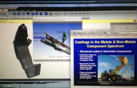
3. Castings-vs-OtherMetal&Non-MetalComponents
Design engineers aren’t generally prejudiced for or against one form of functional or structural component versus another. If they’re good at their profession, they seek robust performance in the lowest cost, final net shape, assembled cost. So, this Segment endeavors to compare all the major ways of forming metal and non-metal components in manufactured products. It also explains in detail what a “Cast Metal” Intermediate Material Shape is. According to NoRedesign.com’s definition, there a several classes of “Intermediate Material Shapes,” such as forgings, fabrications, polymer matrix composites among a few others. The significance of Intermediate Material Shapes is that they have a “pedigree” of their own manufacturing processes, their own material spectrum, and their own tooling...they are NOT commodities. Designing Intermediate Material Shapes requires understanding of that pedigree; otherwise, re-design, schedule over-runs and cost overruns will be the normal consequence. Metalcastings are the most complex, but most powerful among Intermediate Material shapes.
2. Castability Geometry
The next 6 Segments address a foundational premise in NoRedesign’s Cast Metal Intermediate Material Shapes methodology: “Castability Geometry” is shape that is synergistic with a casting alloy’s metallurgical characteristics. There are 5 of these characteristics, and they vary widely across the spectrum of all casting alloys, ferrous and non-ferrous...all the way from gray iron through the light metals, copper-base alloys, steels, and on to super alloys and titanium. Unlike other casting design approaches, which are anecdotal, based on “rules of thumb”... and “just design it like this”... Castability Geometry engages the physics of what is really going on. If Castability Geometry is synergistic with the alloy’s 5 characteristics, the alloy can actually contribute to surface and microstructures integrity. If Castabilty Geometry is wrong, the alloy can’t help.
4. Mold&Cavity-MakingProcesses
This is a highly graphical Segment with videos and animations. This Segment illustrates how all the ways of making metalcasting work is fundamental to both design AND manufacturing engineering of castings. The term “cavity-making” refers to elements assembled into molds to create holes, pockets, re-entrant angles. Generally, in most mold processes, cavity-making elements are called “cores.” In some metal mold processes, the cavity-making elements are mechanically actuated projections into the mold cavity, before mold pouring, that are called “slides.”
5. AlloyCastability&CastabilityGeometry-Overview
This Segment explains the metallurgical basis for the 5 characteristics of metalcasting alloy Castability Geometry, along with how some alloys have favorable “5 characteristics” naturally... like gray iron... and how others are metallurgically engineered to improve the 5 characteristics... like A356 aluminum. Each of the many, many metalcasting alloy families are defined in tables of their 5 Characteristics, and each Characteristic is defined and expressed in examples and pictures. An overview of each Characteristic’s impact on geometry choice is shown in examples.
6. AlloyCastability&CastabilityGeometry-Details
This Segment illustrates with many graphics and animations what each of the 5 Castability Geometry Characteristics look like in actual castings among the various alloy families. This Segment along with the next Segment 7, “Interior Casting Section Junctions” are intended to help the Design Engineer translate differences in the 5 metallurgical “Castability Characteristics” into differences in casting geometry choice.
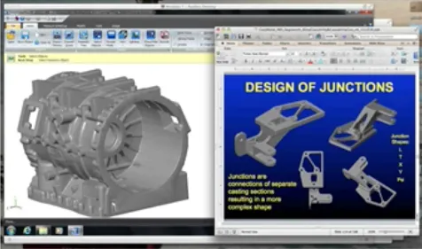
7. AlloyCastability&CastabilityGeometry-InteriorCastingSectionJunctions
Any functional or structural component in a manufactured product, whether metal or non-metal is a geometric coalescence formed from simpler shapes that come together in junctions. Sometimes the junctions are along the perimeter of the coalescence and others are in the component’s interior. Simple examples would be an I-Beam in which 3 rectangles are joined as a center web with a top and bottom flange. The two junctions are along the perimeter of the flanges and those junctions are readily accessible along the outer surface of each flange. However, an X-shape is just two rectangles that cross each other, and their junction is not easily accessible from the perimeter of the X. The junction is in a pocket, no matter how it is approached along the X-profile, and the junction would have to be accessed in another plane, either from the top of the bottom surface of the X.
The essence of Castability Geometry, and how different metalcasting alloys metallurgically adapt to it, is the size, shape, and position of these junctions. This Segment defines the Junction Types and how Castability Characteristics of all the metalcasting alloys react to those types and their specific shapes and locations. Casting integrity, primarily interior microstructure, is highly dependent on the design geometry and the manufacturing engineering of the casting’s Mold & Cavity-Making process. Many graphics and animations illustrate how junctions can be designed to accommodate a particular alloy family’s Castability.
8. ProcessInterfaceGeometry
Mold cavities and their assemblies of Cavity-Making elements, like cores, form the geometry of the component that the Design Engineer intended...with some deviations, like draft, mold parting lines, and core assembly match lines. Another geometry, attached to the mold cavity perimeter, delivers the liquid metal to the mold cavity, and it establishes temperature gradients and mass gradients for solidification. There are also passageways designed into the mold surface...sometimes into the cavity-making elements, too... for evacuation of air and mold material combustions gasses. In the most common metalcasting jargon, Process Interface Geometry is called Gating, Risering, Chilling, and Venting. The terms vary, but Process Interface Geometry is a good global descriptor. Process interface Geometry is the first major intersection between Design Engineering and Manufacturing Engineering (including mold cavity tooling design). Some of the collaborative intersection occurs within the OEM’s Product Launch Team, and even more of it occurs among the Product Launch Team and responding Metalcasting Supplier Teams. Not just the metal caster, but the metalcaster’s partners... especially the tooling builder and machine shop and/or fabricator fixture engineers.
9. IntegrationofMoldProcess&CastabilityGeometry-MoldProcessDominant
Some metalcasting Mold & Cavity-Making Processes affect Castability Geometry significantly. They can dominate some of the 5 Castability Characteristics enough to change allowable casting design geometry. The dominance generally involves mold temperature, mold temperature gradients, liquid delivery and liquid filling dynamics, and/or solidification gradients. Examples of dominant processes are Permanent Mold, ReplicastTM Ceramic Mold, Ceramic Shell Investment, Die Casting... regular, vacuum, and semi-solid, Ablation, and Lost Foam.
This Segment illustrates these dominant processes and how design geometry can be adapted to take advantage of these dominant mold processes’ capabilities.
3. Dimensional Capability
The 6 Segments in this group build an irrefutable argument that Geometric Dimensioning & Tolerancing is the ideal venue for maximizing the as-cast net-shaping capability of the amazing tolerance capability spectrum of metalcasting’s Mold & Cavity-Making Processes. One one hand, the as-cast net shaping capability of the metalcasting processes is unparalleled, however, that capability’s fundamentals are poorly understood by both casting designers and users as well as those who produce them. That lack of understanding... and/or lack of thoughtful application... leads to dimensional approval of 1st Article production castings being typically “last and late” among all other facets of casting specification compliance.
GD&T is not just the venue for net shape dimensions... when innovatively applied, GD&T enables the Process Interface Geometry and Mold Assembly Degrees of Freedom, to be accommodated in mold cavity design among the various Mold & Cavity-Making Process options applicable for a given casting design.
This latter, innovative, manufacturing engineering use of GD&T is an expansion of the following clever sound-bite regarding the Standard: “Geometric Dimensioning & Tolerancing is a contract for inspection, not a recipe for manufacture.”
Tolerance zones of the 5 kinds allowed by GD&T are not only to express allowable imperfection in dimensional form... they also allow space for the Process Interface Geometry “markers” (like gate and riser contacts) and Mold Assembly Degrees of Freedom (like draft, mold element assembly misalignments and joints). It becomes the venue for responding Metalcasting Supplier Team innovation that the Product Launch Team wouldn’t have and probably couldn’t have anticipated. That’s the capability available from the Supply Chain on the right-hand side of the Casting Design Nexus graphic on Page 2 of this summary. “Wide-as-possible” tolerance zones integrated with “narrow-as-required” zones enable the right-hand, Supply Chain side of the Nexus to participate more completely in a manufacturing engineering collaboration over the final solid model.
10. Dimensional Capability Factors Matrix
In this introductory Segment, the principles of dimensional capability are explained. A matrix has been developed summarizing dimensional capability differences, by Mold & Cavity- Making process. The difference between dimensional variation and dimensional centering is defined and explained. Dimensional centering is a more challenging manufacturing engineering problem than variation because Patternmaker’s contraction controls where a dimension’s center resides...and Patternmaker’s contraction cannot be reliably predicted across a complete array of mold cavity dimensions. In a sentence, the mold cavity defines the dimensions of the LIQUID casting; once the solidified casting begins to contract away from the mold cavity walls, the results of that contraction vary across the entire casting geometry. Some behave in the “average” way, and some don’t.
The concept of Mold Cavity Assembly Degrees of Freedom is introduced and illustrated. The Degrees of Freedom add width to the base tolerance variation of the Mold & Cavity-Making Processes...some Processes have more Degrees of Freedom and/or more of it than others.
11. Centering Dimensions within Tolerance Zones
Because of Patternmaker’s Contraction (traditionally called “Shrink Rule”), centering dimensions within specified tolerance bands is a significant manufacturing engineering problem...yet, few casting designs receive the collaborative thought required to minimize centering differences. Minimize is the operative word because Patternmaker’s contraction is estimated, usually by the tooling builder, because its causes of variation are so diverse.
Average Contraction rates vary among all metalcasting alloy families, and average rates vary within some alloy families...like the aluminums and irons. The problem is that the tooling defines the mold cavity which the liquid alloy fills. But that’s not what defines the dimensions...instead, the newly solidified metal contracts away from the mold cavity walls. Where that contraction winds up is complex, and it usually is different from one dimension to another when the mold cavity constraints are different.
Errors in Patternmaker’s Contraction rate estimates are the major reason that dimensional approval in 1st Articles are often “last and late.” Fixing the errors means modifying the tooling, so errors are expensive and take time to fix. But, there are ways to deal with this problem, and how is the subject of this Segment.
12. Power of Geometric Dimensioning & Tolerancing in Casting Dimensional Compliance
This Segment assumes a working appreciation of how GD&T works and its foundational principle of “allowable imperfection.” When metal components are machined complete from a block of wrought metal, the traditional Coordinate Tolerancing method worked reasonably well. The idea of features appearing “perfect,” sometimes located from non-existent centerlines, was workable because the tolerance capability of machining was typically better than the tolerances required. Only a few tight tolerances required more manufacturing engineering thought...and lots of tolerances were forced into the drawing’s Title Block for the convenience of not having to think about it.
But metalcasting surfaces are not so perfect. They have draft, mold parting lines, cavity- making mold assembly element match lines, and Process Interface Geometry “markers”... gate, riser, chill, and vent contacts. GD&T’s 5 tolerance zone types are ideal for accommodating those imperfections, feature-by-feature. GD&T makes designers, manufacturing engineers, metalcasters, mold cavity tooling builders, and machining/fabricating fixture engineers think. With collaborative thinking comes the opportunity to bring the best of the Mold & Cavity-Making processes, the most innovative Process Interface Geometry, and finally...the lowest final-assembled net-shape cost for a high performing, durable component. This Segment gets into the details how that collaborative manufacturing engineering thought process should work and how to incorporate it into the 3rd Generation of the 3 Generations of Solid Models in the NoRedesign Cast Metal Intermediate Material Shapes methodology.
13. Tooling Design for Dimensional Capability
Tooling design and construction for the mold cavity geometry in all its facets is complex. It is central to the collaborative manufacturing engineering methodology encompassed in the 3rd Generation Solid Model development among the OEM’s Product Launch Team and responding Metalcasting Supplier Teams. This Segment examines all of the objectives of mold cavity tooling design and construction, including 1) Part cost..a) As-cast features; b) Upgraded cost of some as-cast surfaces by machining and/or fabrication; c) Final net shape assembled cost; 2) Optimized 3D Area Moment of Inertia...which entirely controls stress and mostly controls defection...for lightweighting and strain life objectives; and finally, and least important...3) Tooling cost. (Tooling cost is sometimes mistakenly prioritized, letting objectives 1) and 2) slip away.) Tooling cost is a capital cost for the whole project, and the benefits of thoughtfully engineered mold cavity tooling design are realized in every casting. Usually those benefits result in lower final total assembled casting cost.
Tooling design and construction latitudes and constraints are examined for each major Mold & Cavity-Making Process. Examples of tooling design and resulting casting capability are shown.
14. Minimizing Machining Set-ups
Metalcastings typically have an amazing percentage of their overall surface used as-cast... that is, the final, assembled surfaces are made net shape directly from the casting process. Typically, the “net shape, used as-cast” percent of surfaces on a cast component ranges from 80% to 90 or 95%. That said, the remaining as-cast surfaces, in most cases, are machined to net shape by removing as-cast material. With the efficiency of today’s machine tools and durable tooling materials, “making chips” is not a significant cost issue. It is highly productive.
What isn’t productive is putting castings manually into fixtures prior to machining. That process is called a “set-up.” Because it is manual and slow, minimizing machining fixture set- ups is a worthy objective in the manufacturing engineering collaboration of the 3rd Generation Solid Model. Design of the mold cavity tooling is integrated with the design of the machining fixture in the manufacturing engineering thought process. A major part of that thought process depends on the capabilities and capitalization of 4 kinds of machine shops. The Metalcasting Supplier Team characteristics of those 4 kinds of machine shops are explained. This Segment is graphical and includes case studies in tooling design to minimize machining fixture set-ups.
15. GD&T-Based Drawings from Solid Models
This Segment clarifies how wide the “wide-as-possible” should be in accommodating the various surface differences that metalcasting mold cavities create. “Wide-as-possible” is a practical manufacturing engineering concept, deviating from the usual “flat-and-perfect” specification for no good reason. Specifically, those real surface profile differences are draft, Process Interface Geometry “markers” (contacts from gates, risers, chills, and vents), and lines from mold assembly joints (parting lines, core assembly match lines, etc). The benefits of allowing “wide-as-possible” are illustrated in examples, and excellence in applying “wide-as-possible” and “ narrow-as- required” is illustrated in well-conceived, GD&T-based solid model drawing output files.
4. Downstream Processing Geometry
Net shape functional and assembly surfaces don’t appear by themselves. They are created by controlling other surfaces in the design of the mold cavity. For example, a curved passageway through a pump is almost always created and used as-cast. And, an important attribute of an acceptable passageway is uniformity of wall thickness around the passageway. The cavity-making mold elements that create that passageway are held in position by other surfaces in the mold cavity that have to be thought about and engineered.
Similarly, other as-cast surfaces have extra material on them to be machined away to form an assembly surface, for example. To machine an assembly surface to net shape means that other surfaces have to be planned and controlled so that a machining fixture can target on them consistently. And, yet other surfaces have to be controlled for clamping against those fixture targets.
These 2 kinds of “other surfaces” are the Downstream Processing Geometry that should be engineered as part of the overall Dimensional Capability plan.
16. Design of Functional Gauges
Functional Gauges are tools used in manufacturing engineering of reliable assembly. Based on Geometric Dimensioning & Tolerancing principles, they are especially powerful in as-cast surface finishing prior to 1) Assembly, using as-cast dimensions; and 2) Upgrading of as-cast surfaces to final net shape by machining or fabricating. In the latter, Functional Gauges assure that as-cast target surfaces will properly align in upgrading fixtures.
Well-engineered Functional Gauges can be combined with a casting finishing process step to make their use more productive. Compared to other process control techniques, Functional Gauges are used on 100% of the castings, in real time... not sampled, and not requiring sample analysis to find out what happened yesterday afternoon... when a defective casting probably has advanced downstream. Castings that don’t pass are immediately set aside for correction or scrapping...ones that won’t assemble properly won’t advance.
Gauge design principles are explained and case studies of actual Functional Gauge designs and just are shown.
17. Design of Fabrication and/or Machining Fixtures...for Reaching Component Net Shape
The Dimensional Capability Principles in Segments 10 through 15 deal with the mold cavity surfaces that are functional, structurally critical in wall thickness, or will be mated with other components in assembly. Some of those surfaces will be upgraded to net shape by removing some of the as-cast surface by machining...or by adding to the as-cast surface by fabrication. As a consequence, most of the casting process and tooling design engineering puts the draft, mold assembly joint lines, and Process Interface Geometry markers on other surfaces. When the primary, controlled as-cast surfaces are upgraded by machining or fabrication, then those other surfaces become important for fixture targeting and clamping. Generally, those surfaces don’t get thought-about until problems develop with castings not resting consistently in the upgrading fixtures.
This Segment teaches how to collaboratively engineer these “other” surfaces with the responding Supplier Teams...especially the mold cavity tooling builder and the machine shop/ fabricator fixture design engineers to engineer inconsistency out of the targeting and clamping surfaces.
Segment 31 is Principles for Prototyping, but as a pre-cursor, this Segment also addresses the “other” surfaces and upgrading fixture design... in the prototyping stage... so that similar consistency can be achieved in net shaping of production castings. The manufacturing engineering forethought to make prototype castings emulate faithfully the eventual production castings dimensionally is not trivial.
5. StructuralGeometry
Since castings have defects to some degree... even though they can be minimized... in their microstructure and possibly on their surface, it is often assumed that castings shouldn’t be designed for long strain life, especially safety critical applications. That assumption, however, is incorrect.
In fact, safety critical, long strain life... even flight critical... castings exist all around us. We have them in the most safety critical components in the cars, light trucks, and heavy trucks that we drive. Jet engine turbine blades are all temperature-resisting super alloy castings. Four-foot (1220mm) diameter (and larger) cast titanium fan frames separate the cold section from the hot section of commercial jet engines and hold the engines to the wings. The F22 Mach 3.5 Stealth Fighter has a number of titanium castings, including the side-of-body castings that hold the wings onto the fuselage. Part of the capability that enables these spectacular structural castings is metallurgical engineering of the melting and solidification processes that minimizes defects. In the case of turbine blades, metallurgical and solidification process engineering eliminates defects while allowing tiny as-cast cooling passages through the center of the blades. BUT, in other safety critical, strain life applications, most of the capability comes from design geometry.
The basis for Structural Geometry’s power in metalcasting structural design has 2 facets:
First, the engineering mechanics of Stress, Deflection, and Crack Formation/Propagation. The fundamental here is Area Moment of Inertia which directly reduces stress, primarily reduces deflection, and significantly reduces the ability of a crack to either form or propagate, if already formed.
Second, is the ability of mold cavity geometry to form Area Moment of Inertia with unlimited shape and variation of shape because the shape is formed in liquid. Along with the unlimited variation in shape, there is also unlimited variation in orientation.
All materials fail in a form of stress that is transformed. For ductile materials... virtually all metalcasting alloys... that transformed stress is Shear, usually referred to as Von Mises Stress. (Brittle materials...a few cast iron alloys...fail in transformed Maximum Tensile Principal Stress.). In either case, complex components loaded with complex forces often have transformed stress occur in oblique orientations.
The mold cavity’s unlimited 3D capability can orient Area Moment of Inertia in exactly the optimal position, shape, and orientation to protect strain life and save mass at the same time.
To clarify that point, it is often mistakenly assumed that reducing Transformed Stress is accomplished by adding mass...instead, it is reduced by adding Area Moment of Inertia. Area Moment of Inertia increases can actually be very light...its the shape, not the mass, that reduces stress. If the Transformed Stress is Shear (Von Mises Stress), a local high stress zone at a surface can actually be dramatically reduced by a tweak in simple cross-sectional area at the correct oblique orientation. That can be very mass-effective.
The most advanced portion of Segment 22 develops a methodology to estimate the oblique angle of Transformed Shear (Von Mises) Stress, for the least mass design that also enables long strain life.
The 6 Segments on Structural Geometry are not intended to teach Engineering Mechanics to Design and Durability Analysis Engineers. They already know that; Rather, it is like a “coloring book” that reminds them of the principles that they know, but don’t often see... because the principles are hidden behind the stress and durability analysis software that they use. The “coloring book” also makes the principles graphical and easy to comprehend for other members of the Product Launch Team whose education doesn’t include Engineering Mechanics. And, it puts the graphical, easy-to-grasp, fundamentals in the context of metal casting’s ability to innovatively develop geometry with infinitely variable shape and orientation to protect critical areas, even if they have minor defects, from too much transformed stress and resulting shorter strain life.
18. Controlling Stress, Deflection, and Cracks
This Segment explains the principles of structural stiffness...stiffness is the fundamental attribute of materials and geometry...that enables components of any type to manage loads safely and with durability. Without repeating the introduction to Structural Geometry above, Area Moment of Inertia is the measure of stiffness in a geometric shape. It’s the reason that an I-Beam is stronger in bending...and lighter...than a simple rectangular bar. And, it’s the reason that a tube resists torque better...while being lighter...than a simple round bar.
There’s another stiffness parameter that’s important in structural design, and that’s the stiffness of the material itself...Young’s Modulus or Modulus of Elasticity. Interestingly, the stiffness of the alloy itself is only involved the equations for deflection... Not for stress... Not for crack formation and crack propagation. English units are handy for this comparison: All the steels and nickel/cobalt-base superalloys have a Modulus of Elasticity of 30 to 34 x 106. But titanium is only 15. Aluminum is 10 and magnesium is 6! So, without Area Moment of Inertia, safety critical aluminum castings wouldn't be possible. Deflection would cause them to strain too much and have low-cycle strain failures.
Like deflection, equations for fracture mechanics look complicated and messy. But the relationship between formation of... or propagation of... a crack and the parameters of its cause is pretty simple. There’s lots of complexity about the mode of the crack formation and the geometry of the crack length and its tip. But, the major factor is the surrounding transformed stress around the crack. We can control that with Area Moment of Inertia. Examples are given of cracks in castings that were expected to form... but didn’t... and a crack that was present, but didn’t grow because the surrounding transformed stress was designed to be low.
Also addressed are Stress Concentration and Residual Stress. This Segment is graphical, colorful, full of examples, and easy to grasp.
19. Alloy Mechanical Properties
Finding and properly applying metalcasting mechanical properties data is surprisingly difficult. This Segment explains why that is, and what the Design and Durability Analysis Engineers can do to find the needed data, how to qualify it in the context of potential microstructure and/ or surface defects, and how to apply it in structural design.
The different kinds of functional, simple structural, and more complex structural data requirements are defined, and the mechanical properties data types are classified to match. Segment 23 addresses the challenge of obtaining very specific data, qualified by defect types and severities, to determine Allowable Transformed Stress (or Transformed Total Strain Amplitude) for structural designs that have strain life objectives.
20. Creating 1st Generation Solid Models via Sketches
NoRedesign’s Cast Metal Intermediate Material Shapes methodology is coalesced in the way solid models are built, analyzed via simulation, and finalized via manufacturing engineering collaboration with responding Metalcasting Supplier Teams. There are 3 Generations of Solid Model development in this process, and the 1st Generation starts with the Design, Materials, and Durability Engineers and the Solid Modeler. This starting point is normal for any kind of structural component made in any material and in any process...but for metalcastings, it should be different.
Despite today’s solid model software having algorithms to easily make swooping, curvy, oblique surfaces, the starting shape is usually blend of simple, orthogonal building blocks... like the way a fabrication is built. To avoid getting “stuck” in an orthogonal, building-block mindset, it would be better to somehow start with a shape that better represents the shaping capability of an innovative mold cavity filled with liquid.
Because of the capability of solid model software to create curvy, oblique surfaces, solid modelers like a proportional, isometric, roughly-to-scale, roughly dimensioned sketch as a starting point for a casting solid model. While Design Engineers usually are quick to make a sketch of an idea they want to express, they are also quick to acknowledge that they aren’t artists. So, how can a Design Engineer make a decent “proportional, isometric, roughly-to- scale, roughly dimensioned sketch?
This Segment illustrates 4 methods of creating such isometric sketches, using clever supporting techniques to draw on, that result in 3D proportionality, scaled shape, and easy dimensioning. The methods also enable visualization of clearance surfaces, assembly surfaces, functional surfaces...like passageways, and Area Moment of Inertia for structural stiffness. Sketching also is an enabler of a talent Design Engineer’s do have...they have a sense scale and shape to carry loads; In other words, they can visualize Area Moment of Inertia in reasonable proportion to carry the loads that they have in their mind for the needed component. Since Area Moment of Inertia always has much more profile for its cross- sectional area than simple shapes, that profile becomes a tool for designed heat transfer in coupling Castability Geometry (from Segments 4 through 9) with Structural Geometry.
21. Qualitative Analysis: Method of Sections
Complementary to the above paragraph’s contention that Design Engineers have intuitive sense of structural size and shape to carry the loads that must be resisted, the ability to make qualitative sketches leading to 1st Generation Solid models is very powerful and time-efficient.
For this reason the Cast Metal Intermediate Material Shapes structural design methodology is qualitative. It leverages the Design Engineer’s intuition...there’s no advantage in trying to calculate using the Old School methods... no advantage to compete with our software tools. So, blend the engineers’ intuition with today’s analysis and simulation software and iterate the solid model structurally from there.
That said, the Old School structural analysis via Free Body Diagrams and the Method of Sections is very helpful...when applied QUALITATIVELY to the initial sketch. This Segment reminds the Design Engineer and the Durability Analysis Engineer of Free Body Diagram and Method of Sections principles... doing so graphically and through examples. It also is presented in a non-quantitative way that should be interesting to other engineering professions in the Product Launch Team.
22. Qualitative Analysis: Uniform Maximum Shear Stress or Total Strain Amplitude
Uniform Transformed Stress across a structural component’s shape, usually most significantly across the shapes surfaces, is the fundamental parameter for least mass. The corollary parameter is the Allowable Transformed Stress for the structural material chosen. In the case of cast metal components, the ability to uniformly control Transformed Stress across a shape, formed so easily as a liquid, enables low density alloys to become more powerful in low-mass, long-strain-life applications.
Software exists to take a solid model, apply a load case, define the material’s Allowable Transformed Stress, and let its algorithm iterate between the solid model’s shape and the Actual Transformed Stress across all of its surface. Where the Actual is lower than Allowable, the algorithm removes mass from the solid model until the shape finally has Uniform Transformed Stress... below the Allowable... all over. The two attributes of the final result are
1. Leastmassfortheloadcaseandthechosenmaterial
2. Ashapethatmustbeacasting,becausethevariationsinshapetomakethe
Transformed Stress uniform are too complex to fabricate...even to machine from a block of wrought metal
This Segment 22 prescribes a relative, qualitative, graphical method, using the Method of Sections and Mohr’s Circle to sketch a preliminary design that is in the ballpark of Uniform Transformed Stress. When the 1st Generation Solid Model is built from that preliminary sketched design, the most important cross-sections will already have the basis for Uniform Transformed Stress when analyzed for Transformed Stress (or Total Strain Amplitude) by durability analysis software. This Segment also emphasizes the iteration of Structural Geometry on the necessary foundation of Castability Geometry to protect the specified level of Allowable Transformed Stress. (Allowable Transformed Stress depends on solidification integrity... which is driven by Castability Geometry in all its facets.)
If Uniform Transformed Stress optimizing software is applied... such as Catia’s Optistruct... the optimization will proceed more quickly because the sketched start was on a sound basis for uniformity among selected critical cross-sections. If regular durability analysis software is applied for integrated improvements aimed at uniformity, the result won’t be optimized, but it will be in the ballpark based on a strong foundational sketch which used Mohr’s Circle to estimate Transformed Maximum Shear (Von Mises) Stress at selected critical cross-sections.
In addition to a quick, intuitive, relative magnitude, qualitative, graphical way to apply Mohr’s Circle to estimate Transformed Shear (Von Mises) Stress at selected critical cross-sections, Part A of Segment 22 also includes a summary of how to use photoelasticity to literally “see” the stress transformation in translucent plastic models of a casting design. An amazing phenomenon that preceded the development of solid models and durability analysis software, photoelasticity is now easily applied to plastic models of casting designs made by the tooling builder of any Metalcasting Supplier Team. For a complex load case, especially one that changes dynamically, preliminary Transformed Stress analysis via photoelastic patterns on a stressed scale plastic model can be a quick, powerful method in developing uniformity in Transformed Stress.
The X-Y-Z coordinate system on which the component design is based, and the load case applied, isn’t the coordinate system of Transformed Stress. The classic stresses, e.g. tensile and compressive stress from bending moments, shear from torsion, shear between load case forces and their reaction forces, and axial stress, that we apply to Free Body Slice Faces in the Method of Sections are also in the X-Y-Z coordinate system. Transformed Stress whether determined from the Von Mises strain energy equations or from Mohr’s Circle is a mathematical transformation. It can’t be visualized in the X-Y-Z coordinate system, but it can be displayed in X-Y-Z. That display is seen as fringe lines on a stressed photoelastic model or as colors representing Actual -vs- Allowable Transformed Stress on a solid model surface.
Although we can “see” the stress transformation on the surface of a component design, that doesn’t mean that the Transformed Stress lies flat on the component surfaces. Part B of Segment 22 addresses another quick, intuitive, relative magnitude, qualitative, graphical method of determining the angle of the plane on which Transformed Stress acts. Knowing that angle, when the transformed stress is Shear, enables minor tweaks in simple cross- sectional area, where the transformed stress is high, so that the casting mass can be the least possible at that cross-section.
Segment 22 Part A is applicable to most structural casting designs in which low mass and long strain life is a sufficient objective. Part B is for a strong, sketched start at a truly uniform Transformed Stress in which least mass coupled with long strain life is the necessary objective... like an airframe structural node.
23. Allowable Maximum Shear Stress or Allowable Total Strain Amplitude
Validation of a structural design, especially one that involves severe service, long strain life durability, and/or safety critical service, is a two step process;
First, simulation of Actual Transformed Stress (Maximum Shear Stress... same as Von Mises Stress... the transformation parameter for all ductile alloys) on the solid model compared to the Allowable Transformed Stress, usually expressed as colors across the surface of the solid model.
Increasingly, those simulations of stress transformation are expressed as Actual -vs- Allowable Transformed Total Strain Amplitude because of the dramatic increase in long-strain-life structural application of strain-sensitive light alloys, like aluminum.
Second, component testing to verify the simulation results. Since durability testing is so expensive and a significant part of the Product Launch Timeline, being confident of transformed stress or strain simulation results is very important.
The capability of the software to accurately simulate the Actual Transformed Maximum Shear Stress or Total Strain Amplitude is robust. The physics is well-established and the algorithms are proven.
However, for metalcastings, determining the Allowable Transformed Stress or Strain value is a challenge. Without a believable Allowable value input into the software, the simulation results are not worthy of confidence when moving a metalcasting prototype into durability testing.
This Segment uncovers, explains, and illustrates a long-forgotten tool for analyzing component durability in terms of the load case R Ratio and defect types present in a metal component, either in the microstructure or on the surface. Unlike Stress -vs- Number of Cycles charts for fatigue life...or Total Strain Amplitude -vs- Strain Reversals to Failure...the Goodman Diagram displays Allowable Transformed Maximum Shear Stress for an established number of fatigue cycles. The variables are load case R Ratio and the type and severity of casting defects, either in the microstructure, on the surface, or both. The power of the Goodman Diagram is its ability to enable Allowable Transformed Maximum Shear Stress data that doesn’t match your exact R ratio or microstructure/surface integrity level and convert it to Allowable values that DO match. The match is an engineered judgment, but far more accurate... and aligned better with reality... than a coarse contingency factor or traditional safety factor applied grossly to the Transformed Yield Stress for unknown factors.
In addition to a methodology to estimate Allowable Transformed Maximum Shear Stress (Von Mises Stress) for traditional fatigue life, Segment 23 also details Goodman Diagram-based methodology to determine Allowable Transformed Total Strain Amplitude -vs- Strain Reversals. Total Strain Amplitude is the better parameter to evaluate structural designs because it enables design for any planned level of strain reversals. It also recognizes that most alloys don’t actually have a “Fatigue Limit” like the steels do. While superior data, the problem with Transformed Total Strain Amplitude is that the curves have been established for near-perfect casting test coupons. And the R ratio is almost always the standard “most severe,” fully reversing, negative 1.0. If your casting is NOT perfect in microstructure or surface integrity, how can you modify the strain life equation coefficients for your real situation? Segment 23 has the answer to that problem.
While durability analysis software is spectacularly capable at estimating Actual Transformed Stress or Total Strain Amplitude, Allowable is just a number someone inputs into the software. If Allowable doesn’t represent reality from the Load Case R ratio, reality from the design life, and reality from casting integrity, then those colors on the solid model surface don’t mean much!
6. IntegrationofPrinciples;PartI
24. 1st Generation Solid Models
The purpose and principles of 1st Generation Solid Model development is documented in prior Segments, those in Castability Geometry Group, Dimensional Capability Group, and Structural Geometry Group. This segment details the collaborative process within the OEM’s Product Launch Team to develop the initial and interactive versions of the 1st Generation Solid Model. The Professions involved in the initial model are Design Engineering, Materials Engineering, Solid Model Building, and Durability Analysis Engineering.
The iterative process in the 1st Generation Solid Model is based on simulations of mold filling and solidification after Process Interface Geometry has been added to the “naked” initial 1st Generation Solid Model. Manufacturing Engineers take the lead in this phase of model development. Results of simulation will not only modify the mold cavity features of the 1st Generation “naked” model but also the Liquid Delivery Geometry (Gating), Temperature/Mass Gradient Geometry (Risering), Mold Interface Temperature Gradients (Chills, Cooling Lines, Exothermics), and Gas Evacuation Interfaces (Vents) which eventually will compose the 2nd Generation Solid Model.
The collaborative process developing the 1st Generation Solid Model... from the early brainstormed sketches ...to the Version 1 1st Generation Solid Model is aimed at successfully overlaying the Functional Geometry, especially the Structural Geometry, on the necessary foundation of Castability Geometry. As explained in the Segments of the Castability Geometry Group, if mold cavity and its internal geometry junction geometries don’t match what the selected alloy “likes,” then solidification integrity will suffer. That means that solidification defects might appear in a machined functional surface or might reduce the Allowable Transformed Stress in a critical structural region.
So, simulations of solidification on a sequence of “naked” 1st Generation Solid Model versions is really important to prove that the Castability Geometry foundation is capable of supporting the Functional and/or Structural objectives. Then additions of simple Process Interface Geometry (gates and risers) to simulate mold filling temperature distributions prior to solidification simulation enables further refined versions of the 1st Generation Solid Model. The objective is a refined blend of geometries that results in solidification and surface integrity that complies with the casting’s performance specifications.
25. Geometry Examples; By Alloy Family
Since Castability Geometry, based on it’s 5 metallurgical characteristics, varies so much by Alloy Family, looking at examples of Functional and Structural designs in those families is instructive. Commentary about similarities and differences is provided.
26. Geometry Examples; By Application Industry
Cast Metal Intermediate Material Shapes instruction is full of examples distributed across the Segments that define principles and explain methodology. By definition, Design Engineers and their Product Launch colleagues work in a manufacturing industry in which applications are similar. So, seeing examples of successful casting designs, serving their specific industry, is helpful, along with commentary about the similarities in function, structure, and design approach.
27. Conversions to Castings: Fabricated and Machined-from-Wrought Components
A fundamental in well-executed casting design...and documented in Segment 1 - Management Overview...is that design of castings can help manufactured products capture margin... and manufacturing engineering of casting processes can protect margin. A proof point of that fundamental is that so many existing components that were originally fabricated or machined from a blank of wrought metal are successfully converted to to castings. Since the conversion has its own costs...engineering time, supply chain engagement, new tooling, prototypes, and 1st Article approval, there must be a lot of margin left on the table when the component was not a casting in the beginning.
This segment summarizes the capabilities of fabrications and machined-from-wrought stock components and why they get designed that way, first. Also summarized are their drawbacks which ultimately initiate a conversion design into a casting. Many examples are shown of original fabricated or machined-from-wrought components and the eventual casting conversion...in a variety of alloys and Mold & Cavity-making Processes.
The methodology of the engineering thought process is also explained graphically, with examples, using Cast Metal Material Shapes principles to make the casting conversions. One interesting case study illustrates a single fabricated design and multiple, valid ways to convert the component to a casting...some ways more optimal than others. That, too, illustrates a Cast Metal Intermediate Material Shapes methodology fundamental: Make a lot of iterations in the early 1st Generation Solid Model development. Since so many ideas are possible, don’t settle too quickly on one that is sub-optimal when a great idea is just another thought away or just a good suggestion from a colleague waiting to be listened to.
7. IntegrationofPrinciples;PartII
28. 2nd Generation Solid Models
29. 3rd Generation Solid Models - Baseline Models
30. 3rd Generation Solid Models - Response Models
The purpose and principles of 2nd and 3rd Generation Solid Model development is documented in prior Segments, those in the Castability Geometry Group, the Dimensional Capability Group, and the Structural Geometry Group. These groups of segments detail the collaborative process within the OEM’s Product Launch Team to develop the initial and in- house interactive versions of the 1st Generation Solid Model and improve it through mold filling and solidification simulation of the 2nd Generation Solid Model.
According to the principles and methodology in the Dimensional Capability Group, the Product Launch Team’s iterations between the 1st and 2nd Generation Solid Model finally results in a “naked” 1st Generation Solid Model for which the software generates a drawing output file. That drawing is toleranced using GD&T, according to our “Wide-as-Possible” tolerance zones, defined feature-by-feature along with the “Narrow-as-Required” tolerance zones. The result being a “contract for inspection, not a recipe for manufacture” through which the solicited Metalcasting Supplier Teams can apply their Mold & Cavity-making Processes to comply with the “Narrow-as-Required” zones and use the “Wide-as-Possible” zones to locate their Process Interface Geometry and allow their Mold Degrees of Freedom to coarsen tolerances where it doesn’t matter functionally, structurally, or in assembly.
The Metalcasting Supplier Teams’ use of those two types of tolerance zones (offered to them in the 3rd Generation “Baseline” Solid Model in solicitation) finally results in a 3rd Generation “Response” Solid Model...which each responding Supplier Team submits...fully GD&T toleranced. The process from the 3rd Generation Baseline Solid Model solicitation to the final, fully-developed Response Solid Model is collaborative between the OEM’s manufacturing engineers and each Metalcasting Supplier Team... separately and in confidence.
Among those separately-developed Response Solid Models... with their toleranced drawing output files... the OEM’s manufacturing engineering function recommends to Procurement their suggestion of the best two or three responses, and Procurement makes the Supplier Team choice. The major benefit of this collaborative process is a indication to the OEM manufacturing engineers of Supplier Team manufacturing capability, and Procurement sees indications of “Should Cost” rather prices of unknown basis and little substantiation.
These Segments take the engineering principles in prior Segments and focus on the “how to actually do it” collaboration and management elements.
31. Principles for Casting Prototypes
Prototyping castings is far more complex than prototyping other metal component forms... and probably more complex than most non-metal component forms. The reason is embodied in the name of this instructional product: “Cast Metal Intermediate Material Shapes.” An “Intermediate Material Shape” is a component type, metal or non-metal, that has manufacturing process and tooling design/construction pedigree. It is far from a commodity, and it’s properties and capabilities are the result of its manufacturing process and tooling heritage.
Both prototype and production castings have this pedigree. The complexity in prototyping is not just that engineering of the pedigree must be actively engaged, but also that the pedigree is often different for prototypes. Prototypes probably will have a pedigree that is different than the eventual production casting pedigree. That probability requires careful manufacturing engineering thinking and planning.
Why does a different pedigree matter? Most significantly, prototype structural castings must be representative of the eventual production castings’ solidification integrity. Allowable Transformed Stress is dependent on the casting’s solidification integrity, and it is the prototype castings that are subjected to durability testing. A challenging scenario often occurs when an aluminum, long-strain-life, structural casting is to be produced in an advanced form of the Permanent Mold Process but prototypes can’t wait for... nor can afford... the eventual tooling design and construction... nor can wait for or afford the production
Permanent Mold Process. So, how can prototypes be made that will be representative of the solidification integrity of eventual production castings? This Segment addresses how.
The different pedigree of prototype Mold & Cavity-Making Process and tooling design/ construction may also affect dimensional compliance and cosmetic appearance.
The nearly universal present practice of OEM’s designing castings in a “closet” and then announcing result in a solicitation with a solid model, a toleranced drawing output file, and a list of specification has one nearly universal result: Little time to do thoughtful manufacturing engineering of the prototype Mold & Cavity-Making Process and tooling design/construction... once a Metalcasting Supplier Team is chosen.
The Cast Metal Intermediate Material Shapes methodology, culminating in the 3rd Generation Baseline and Response Solid Model collaboration, enables the time for thoughtful manufacturing engineering, and it enables parallel prototyping process proposals among competing Metalcasting Supplier Teams.
Much of this segment is devoted to the differences between prototype and production Mold & Cavity-Making Processes and how to use manufacturing engineering of tooling design and construction for the mold cavity to mitigate the differences.
A very interesting new technology, that has made a huge impact on mitigating those differences, is the application of Additive Manufacturing to direct computer formation of mold cavity elements in sand, plaster, or metal. Metalcasting Supplier Teams’ tooling builders have access to (and often actually have) Additive Manufacturing technologies, and they can make prototype mold elements that eliminate draft, eliminate or minimize Mold Degrees of Freedom, and change heat transfer rates on selected mold cavity walls. Additive Manufacturing technologies applied to manufacturing engineering of casting prototype mold cavities may be the least known, but most powerful application of Additive Manufacturing.
8. CastingCost
32. Mitigating Casting Cost Drivers
Casting cost is most near and dear to the Metalcasting Supplier Teams because it, relative to price, determines the margin that they can share. Casting users have a vested interest, too. Most manufactured products have trouble launching on time with components that meet cost objectives and on-time Production 1st Article approval. Metalcastings have more of that launching trouble than other engineered component types... and preventing that is the whole premise behind NoRedesign.com's approach to the design and manufacturing engineering of castings.
So manufacturers legitimately want to know what castings really cost so that they can negotiate price reductions to recover their planned margins, after production has reached steady-state.
Traditional attempts at defining and prioritizing casting cost elements are illustrated in this Segment, and the most significant shortcoming is always, “To what alloy family and what Mold & Cavity-Making Process do these cost elements apply?” Usually the author of such casting cost profiles is thinking that the cost structure of other alloy families and processes are similar in cost structure. Some are, but many are not.
This Segment offers analysis of elements of casting cost with two better approaches:
1. A table of casting cost elements expressed in terms of Total Final Assembled Cost. Included are the fixed and variable costs incurred by the Metalcasting Supplier Teams. Also included are the fixed and variable costs incurred by the OEM, such as freight, inventory, final processing, and assembly.
a. The best question about these cost elements should be,“Which among these cost elements... either on the Metalcasting Supplier Team side or the OEM side of cost... could be reduced through efficiency or a specification change so that margins on both sides can be protected.
b. Another question that may be worthy is,“Can the tooling and/or the Mold & Cavity- Making Process be changed to achieve a dramatic cost reduction?” If so, the capital cost to the OEM and the manufacturing engineering cost investment by both parties can realize a return on investment in every casting produced and sold.
2. “ShouldCost”is concept that has developed in recent years, seeking computer algorithms that could take a description of a component, its specifications, and its manufacturing process and spit out a “Should Cost” median value and a narrow range high to low values.
a. Attempts, even with relatively simple manufacturing processes, haven’t been
successfully accurate yet
b. Metalcasting specifications and manufacturing processes are so complex and varied,
that a successfully accurate algorithm is highly unlikely
c. However, the manufacturing engineering collaboration professed in our Cast Metal
Intermediate Material Shapes 3rd Generation Baseline and Response Solid Model methodology does result in a glimpses of “Should Cost” because it requires demonstration of Metalcasting Supplier Team manufacturing capability.
Even if an accurate “Should Cost” algorithm existed for metalcastings, by the time all the algorithm inputs could be investigated and applied, our 3rd Generation Solid Model collaboration methodology could have played out. And, multiple “Should Cost” responses result, not just one, based on the various manufacturing approaches that the 3rd Generation Solid Model methodology encourages.
So, one option that an OEM could choose for evaluating cost reduction on a metalcasting already in production is to review the alternate proposals from the Metalcasting Supplier Teams when the casting was originally solicited.
Another, option, probably more likely, is to engage the winning Metalcasting Supplier Team in a new collaboration of the design requirements and the full spectrum of manufacturing processes on both sides to seek mutual cost reduction benefit... while protecting, or even increasing, margins.
This Segment 32 explains the elements of casting cost and describes ways to prioritize and analyze them for mutual casting producer and casting user benefit.